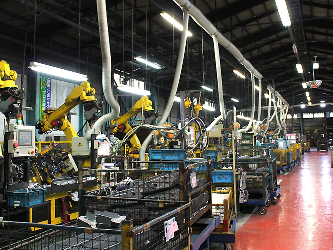
VFD failures have a very narrow set of causes: poor cooling accounts for over half, and most of the rest are wrong parameters or supply problems. With proper care, service life goes from three to five years to over eight.
VFDs have internal fans, and fans are wear parts. Replace them at 20,000–30,000 running hours (about three years of continuous duty); do not wait for one to seize. Once a fan stops, capacitor and IGBT temperatures climb fast — first over-temperature alarms, then a blown drive.
Clean dust off the heatsinks regularly. In dusty locations clean every three months, using low-pressure compressed air with a vacuum running alongside. Wash cabinet filters monthly.
Keep the cabinet below 40 °C. In hot shops during summer, consider a cabinet air conditioner or heat exchanger. Every 10 °C higher inside roughly halves electrolytic capacitor life.
Electrolytic capacitors are the VFD's life-limiting component. Judge them by: bulging or leaking cases, DC bus voltage ripple, or the drive's built-in capacitor life monitor (many brands have one). Once capacitance has fallen more than 20%, plan the replacement.
 FIELD · SCHH-2026
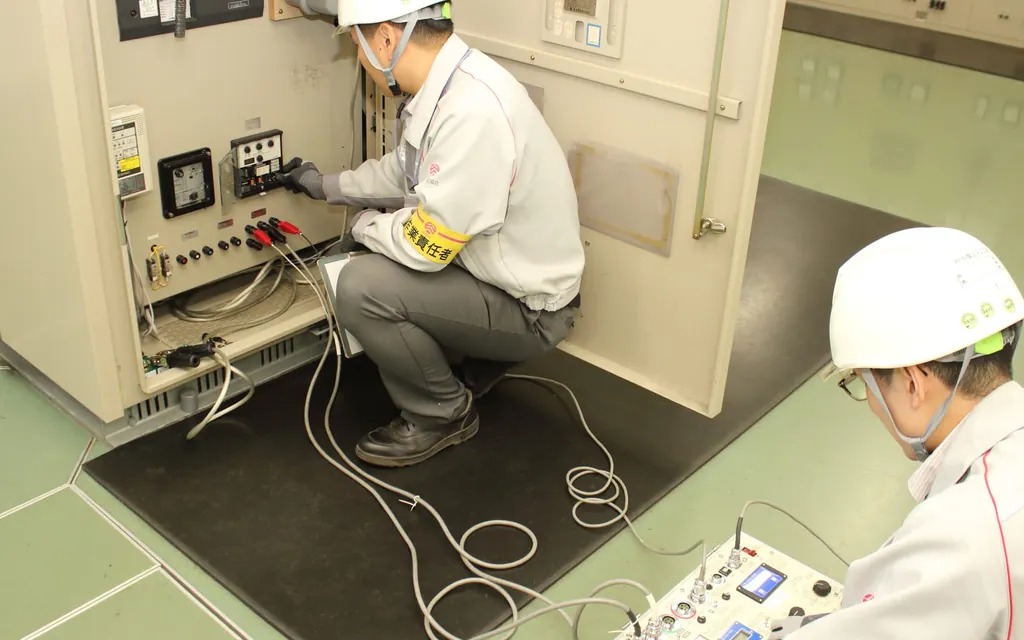
Record every parameter — especially motor nameplate data, ramp times, overload protection settings, and V/F or vector control parameters. When replacing a drive, a parameter sheet means the job takes half an hour; without one you commission from scratch.
Motor nameplate parameters must be entered exactly. Errors throw vector control off, heat the motor up, and make protection unreliable. After any motor change, re-run parameter identification (auto-tuning).
Do not set ramp times too short. Short ramps swing the DC bus voltage harder, age the capacitors faster, and trip on overcurrent more readily.
Never loosen protection settings casually. Overcurrent, overload and over-temperature protection exist to protect the equipment; widening them is the same as removing them. Frequent trips call for a root cause, not a parameter change.
 FIELD · SCHH-2026
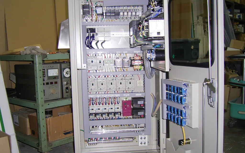
Supply voltage must stay within tolerance (generally ±10%); beyond 3% phase imbalance, fit a line reactor. An unbalanced supply enlarges DC bus ripple, hurting both capacitors and the rectifier bridge.
Where several drives share a busbar, fit line or DC reactors — they suppress harmonics and protect the rectifier bridges. In heavily distorted supplies (many drives on one transformer), consider active filtering.
Never add capacitors or power-factor correction on a drive output — it destroys the drive outright. For long motor cables (generally over 50–100 m) fit an output reactor or dv/dt filter, or overvoltages will break down the motor insulation.
Use shielded cable between drive and motor, with the shield earthed at both ends (360° termination at the drive) — a safety requirement and a must for interference suppression.
| Maintenance item | Interval | Method | Acceptance criteria |
|---|---|---|---|
| Filter cleaning | Monthly | Intake filter | No dust blockage |
| Heatsink cleaning | Quarterly (monthly in dusty settings) | Compressed air + vacuum after isolation | No dust between fins |
| Cabinet temperature record | Weekly | Temperature check at full load | < 40℃ |
| Cooling fan operation check | Monthly | Listen and watch the speed | Runs smoothly, no abnormal noise |
| Fan replacement | At 20,000–30,000 running hours | Replace as a set | Replace on schedule; never wait for seizure |
| DC bus voltage / capacitor condition | Annual | Panel readings; visual check for bulging or leakage | Normal ripple, no bulging |
| Parameter record and backup | After every change | Full parameter sheet on file | Fully recoverable |
| Terminal tightening | Semi-annual | Main and control circuit terminals | Torque to spec, no discolouration |
Drive faults sort by root cause into three families, and with the family clear, troubleshooting has direction. Family one, environment: poor cooling (blocked air paths, dirty filters, aged fans) causing over-temperature trips; dust and moisture causing module breakdown and spurious operation; poor supply quality (voltage swings, harmonics, lightning) damaging the rectifier and inverter sections. Environmental faults are the majority - and almost all are preventable. Family two, parameters: accel/decel times set wrong causing overcurrent or overvoltage; V/F curve mismatched to the motor causing heat and weak torque; protection parameters too loose or too tight causing failure to act or nuisance trips; parameters lost or never backed up, making a replaced drive impossible to restore. Family three, load: mechanical jamming causing stall overcurrent; load transients exceeding drive capacity; current anomalies from transmission faults (slipping belts, damaged couplings).
The recommended troubleshooting order is "classify the symptom first, then check the matching stage": over-temperature trips point to environment and cooling; overcurrent trips start with the load (uncouple and test no-load), then parameters; overvoltage trips point to the supply and decel time; undervoltage to supply and rectifier; communication faults to wiring and interference; a dead display to supply input and the precharge circuit. This order covers the great majority of field cases and is far faster than testing modules one by one.
One more rule of thumb worth remembering: after a drive fault, do not immediately reset and restart three times. Repeated reset-and-energize can escalate a repairable fault into a blown module. The right response is to power down first, check the externals (load, supply, environment), eliminate the obvious causes, then energize once more as a test. If it still trips, hand it to a professional - do not gamble with the equipment.
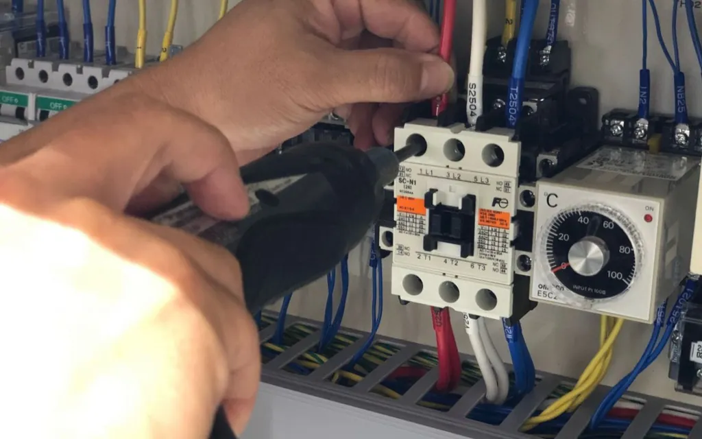
A drive's life bottleneck is mainly its electrolytic capacitors and cooling fans: design life under normal duty is roughly five to ten years, but temperature dominates - every 10°C rise in cabinet temperature approximately halves capacitor life. Ways to judge aging: measuring DC-bus capacitance (with a dedicated meter or by lab test), measuring running ripple voltage, visual inspection (bulging, electrolyte leakage, relief-vent operation marks), and fan noise and airflow. Our recommendation is a capacitor-and-fan assessment for critical drives after five to eight years of service; the assessment data decides whether to replace fans and capacitors or the whole drive - fan and capacitor replacement costs far less than a new unit, so extend service wherever possible.
 FIELD · SCHH-2026
It depends on system scale and sensitivity. A single small drive usually has limited impact; where multiple large drives are concentrated, harmonics cause excessive neutral current, capacitor heating, extra losses in transformers and cables, and maloperation of sensitive equipment. Mitigation options in ascending cost: input AC reactors (low cost, limited suppression), multi-pulse rectification or AFE active front ends (effective, expensive), and active filters (highly targeted, highest investment). Whether treatment is needed must be measured: harmonic current distortion, neutral current, capacitor temperature rise. On our energy and power-quality projects we measure first and then define the plan - we do not sell filters blindly, and in many cases an input reactor is all that is needed.
Drive parameters are managed in three classes by importance. Class one - must be recorded and reproducible: motor nameplate data (power, voltage, current, frequency, speed), control mode (V/F or vector), accel/decel times, protection settings (overcurrent, overload, overheat), and communication parameters (station address, baud rate, protocol). Lose these and the drive essentially cannot be restored to its function. Class two - process parameters worth recording: multi-speed settings, PID parameters, frequency limits, terminal function definitions. Class three - factory defaults: generally no need to record, but note whether they were modified.
The backup method depends on the drive model: those with keypad storage can be copied panel-to-panel; those with communication ports can be uploaded via software; for neither, at minimum photograph or transcribe the key parameters and file them. Name backup files with equipment number and date, linked to the equipment file. On our retrofit and maintenance projects, parameter backup is a standard deliverable, and the delivery list states where the backup files are kept and how to restore them.
Parameter changes require discipline: record the original values before the change, verify the effect after it, and only on successful verification confirm the change and update the backup. Ad-hoc parameter edits under production pressure are a major hidden hazard - changed with no record, verified by no one, and at the next failure nobody knows the parameters were touched. Writing this rule into the equipment management system is far less effort than after-the-fact investigation.
 FIELD · SCHH-2026
This article was written in-house by the Industrial Equipment Services Division. The thresholds, intervals and scrap criteria are field-experience values; in practice follow the equipment manufacturer's technical documents, current national standards and special-equipment safety regulations. Inspection and testing of special equipment (cranes, pressure vessels, etc.) must be carried out by a qualified body.
Send us your equipment list and operating conditions, and we will give you a workable inspection and maintenance standard.
 Scan to add Engineer Man on WeChat
 Guangzhou Yujihang Computer Technology Co., Ltd. · www.accpc.com.cn
 Guangzhou Henghuan Technology Co., Ltd. · www.hhrobotics.cn
 Nanchong Henghuan Robotics Co., Ltd. · www.hhrobots.cn