A hydraulic system that feels weak and runs hot usually has one cause: wrong pressure settings or excessive internal leakage. Diagnosis has to follow a sequence, otherwise you replace a round of parts and nothing changes.
The system pressure only needs to sit 10–20% above the true maximum working pressure — higher is not better. Set too high, the excess all turns to heat across the relief valve: oil temperature soars, energy use climbs, and component life shortens.
To find the real requirement: read the machine manual, or measure each actuator's actual working pressure during normal operation and take the maximum plus margin. On many old machines, successive maintenance crews have cranked the pressure up and up until it far exceeds the design value — a major source of heat.
After lowering the pressure, verify: are movement speeds adequate, can it still lift the maximum load, do all movements complete fully? If everything is normal, the setting really was too high.
 FIELD · SCHH-2026
Internal leakage has a classic signature: slow movements, pressure that will not hold, high oil temperature, yet pump outlet pressure still builds. Locate it by isolating sections.
First test the pump's volumetric efficiency: fit a flowmeter at the pump outlet and compare unloaded and loaded flow, or simply watch how fast the gauge falls while holding pressure. Heavy pump leakage means slow pressure build-up and fast pressure decay.
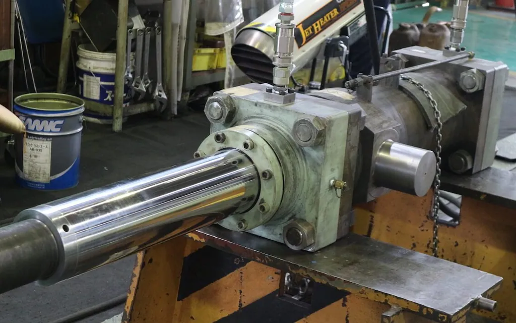
Then check the actuators. For a cylinder: with the rod fully extended, disconnect the rod-side return line and see whether oil keeps flowing (normally there should be almost none). A steady flow means the piston seal has failed.
Last, check the valves: internal leakage in the relief, directional and check valves. A relief valve that will not seat shows as pressure that cannot be set high, or that creeps down; a directional valve leaking in centre shows as an actuator that will not hold still and drifts.
 FIELD · SCHH-2026
When the system is idle, the pump output is either unloaded to tank or held against the relief valve. Continuous relief under pressure is an enormous heat source. Where a machine idles for long stretches, add an unloading circuit (solenoid relief unloading, accumulator hold, etc.) — it saves power and cuts heat.
An accumulator greatly cuts relief time. Check its pre-charge: nitrogen pre-charge is generally 80–90% of the system's minimum working pressure, measured with the proper charging tool. Wrong pre-charge makes the accumulator useless and can cause pressure shocks.
Proportional and servo valve systems deserve special care: these valves demand very high oil cleanliness, and a sticking spool causes pressure faults and lost motion. Check the oil first, then the valve, and only last the electrical signal.
Only after the earlier causes are ruled out, and oil temperature is still high, look at the cooling system. Water-cooled: check water flow, inlet temperature and heat-exchanger scaling. Air-cooled: check fan direction and speed, whether the fins are blocked, and ambient temperature.
The cooler was sized for the design duty. If the machine has since taken on more load (extra actuators, a faster cycle), the original cooler may be undersized — that needs recalculation, and cleaning alone will not fix it.
Consider tank volume and heat-dissipating area too. A tank that is too small cycles the oil too fast, leaving no time to shed heat or settle contaminants. As a rule of thumb, effective tank volume should be 3–5 times the pump's per-minute flow.
| Maintenance item | Interval | Method | Acceptance criteria |
|---|---|---|---|
| System pressure setting check | Yearly / after modification | Against design value and measured need | 10–20% above max working pressure |
| Pump volumetric efficiency test | Annual | Flowmeter, unloaded vs loaded flow | Efficiency drop <10% |
| Cylinder leakage check | Semi-annual | Hold pressure, watch return flow | No continuous leakage |
| Relief and directional valve function test | Annual | Pressure stability, centre-position hold | Pressure holds, no drift |
| Accumulator pre-charge pressure | Semi-annual | Measured with the charging tool | 80–90% of min working pressure |
| Cooler efficiency check | Annual | Oil temperature drop; water / air flow | Temperature drop to design |
| Unloading circuit function check | Semi-annual | Pressure and current when idle | Unloads properly when idle |
The most common mistake in hydraulic troubleshooting is "guessing components" - hearing that pressure is low, suspect the pump; hearing that motion is slow, suspect the cylinder; then start stripping. When it turns out not to be that one, guess the next, and days pass with nothing located. A systematic diagnosis works top-down: system parameters first (pressure, flow, temperature, current), then circuit isolation (are all motions abnormal or just one), then components, and teardown confirmation last. This order avoids the great majority of pointless disassembly.
The circuit-isolation step is especially critical. When all motions are abnormal, the problem is in a shared element - pump, relief valve, system pressure setting, oil condition. When a single motion is abnormal, the problem is in that motion's dedicated components - its directional valve, flow control, cylinder or check valve. With this bisection, the suspect list shrinks by more than half immediately. For example: a machine with three motions where only one is slow - pump and main relief valve are ruled out, and only that circuit's valve and cylinder need checking.
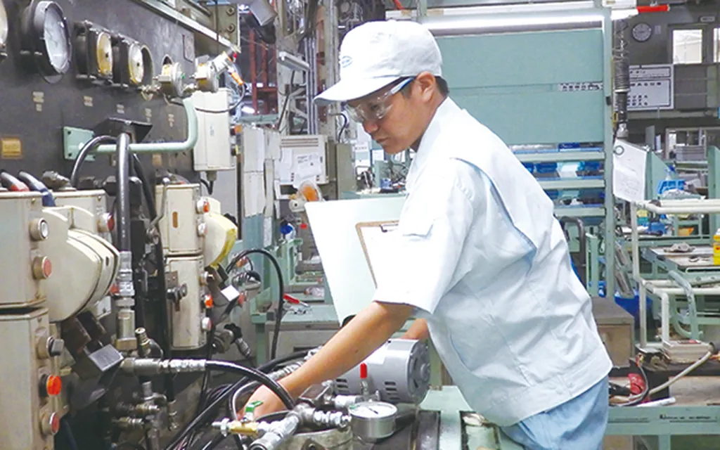
The value of parameter measurement cannot be overstated. With pressure gauges and a flow meter, judgments have a basis; relying on feel and sound alone, accuracy depends on experience and cannot be passed on. We recommend permanent gauge ports (or temporary connections) at key points of hydraulic systems, and three readings taken first in any diagnosis: system pressure (compared with the setting), pressure behavior during motion (load magnitude and relief condition), and pump outlet flow (volumetric efficiency). These three cover the judgment needs of most faults.
Normal pressure means the pump and relief valve are basically fine; weak motion points to flow or internal leakage. The check order: first, internal leakage in that motion's circuit (worn directional valve spool, worn cylinder piston seals - judged by a pressure-hold test: hold pressure after the motion reaches position and watch the decay rate); second, flow supply (throttle valve opening, flow-control setting, actual pump flow); third, whether the load has changed (mechanical binding, increased friction, overload). Most cases turn out to be cylinder piston-seal internal leakage, showing as slow motion plus rising oil temperature - because the energy of the internal leak turns into heat.
 FIELD · SCHH-2026
The recommended working temperature for ordinary hydraulic systems is 30-55°C; sustained operation above 60°C must be treated as abnormal: oil oxidation accelerates (roughly doubling per 10°C rise), seals age, and falling viscosity increases internal leakage - a vicious cycle. Treat it in four steps: first find the heat source (measure temperatures at each point and judge whether it is relief loss, throttling loss, internal leakage or insufficient cooling); then check the cooling system (cooler blocked? water and airflow adequate? temperature control valve working?); then treat the losses (is the pressure setting too high, is the system relieving continuously, is component internal leakage severe?); and only last consider adding cooling capacity. Reverse the order and money is wasted - most of the high-temperature cases we have seen trace to a pressure setting too high and a dirty, blocked cooler, both cheap to fix.
Basic tools solve most field diagnosis: pressure gauges (system and circuit pressure), thermometers (infrared or probe), a flow meter (actual pump output and circuit flow), and a stopwatch (motion times compared against standard). The investment is small, but with these four, diagnosis shifts from "guessing by experience" to "judging by data". Motion timing is especially valuable - how long one motion takes from start to finish, compared with its normal value, is the most direct way to judge internal leakage and insufficient flow: zero cost and repeatable.
Advanced methods are introduced as needed: pressure-hold testing (judging internal leakage by plugging and measuring decay rate after a motion reaches position), a vacuum gauge (suction-side vacuum, judging restricted suction), oil analysis (cleanliness, viscosity, water content - overall system health), and a component test stand (offline performance testing of valves and pumps, requiring professional equipment). Most of these are used only in professional maintenance; for daily diagnosis, the basic four tools plus sectional-test thinking are enough.
The value of diagnostic records deserves separate emphasis: for every fault, record and file the symptoms, measured data, reasoning process, corrective actions and replaced components. After three months you have a failure-mode library - which fault types recur, which components have short lives, which parameters drift easily. That library is direct input to the preventive maintenance plan and the best training material for new staff. What most plants lack is not diagnostic ability but the habit of keeping diagnostic experience on record.
 FIELD · SCHH-2026
This article was written in-house by the Industrial Equipment Services Division. The thresholds, intervals and scrap criteria are field-experience values; in practice follow the equipment manufacturer's technical documents, current national standards and special-equipment safety regulations. Inspection and testing of special equipment (cranes, pressure vessels, etc.) must be carried out by a qualified body.
Send us your equipment list and operating conditions, and we will give you a workable inspection and maintenance standard.
 Scan to add Engineer Man on WeChat
 Guangzhou Yujihang Computer Technology Co., Ltd. · www.accpc.com.cn
 Guangzhou Henghuan Technology Co., Ltd. · www.hhrobotics.cn
 Nanchong Henghuan Robotics Co., Ltd. · www.hhrobots.cn